Skip to content
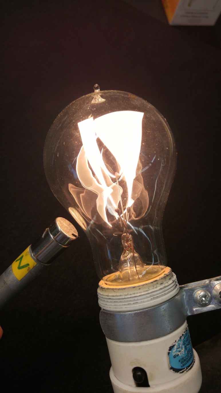

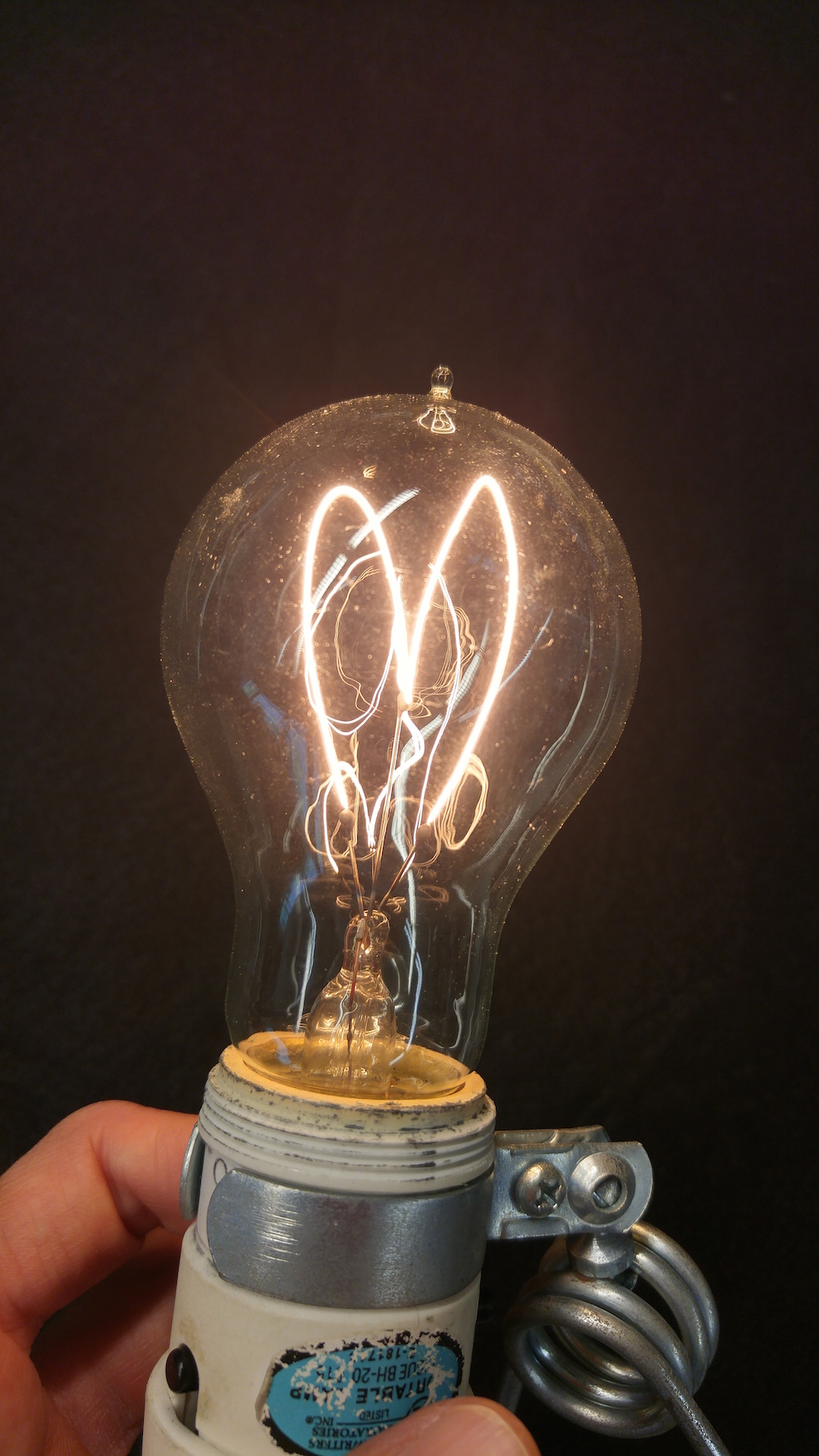
- The Victorian light bulb (a replica of Thomas Edison’s original design) contains a long, visible, carbon filament.
- When a neodymium magnet is brought into close proximity of the bulb, the field of the magnet causes the filaments to vibrate at 60 Hz (the frequency of AC current in the filaments).

- Bulb located in L01, section B3 (in a small, labeled box).
- Lamp cord in L35, section D2.
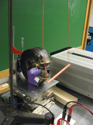

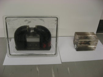
- Straight, rigid wire hangs between poles of strong magnet.
When current is sent through wire, wire is deflected. Direction of deflection
depends on direction of current.
- For setup assistance, ask Lab Lecturer.
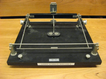


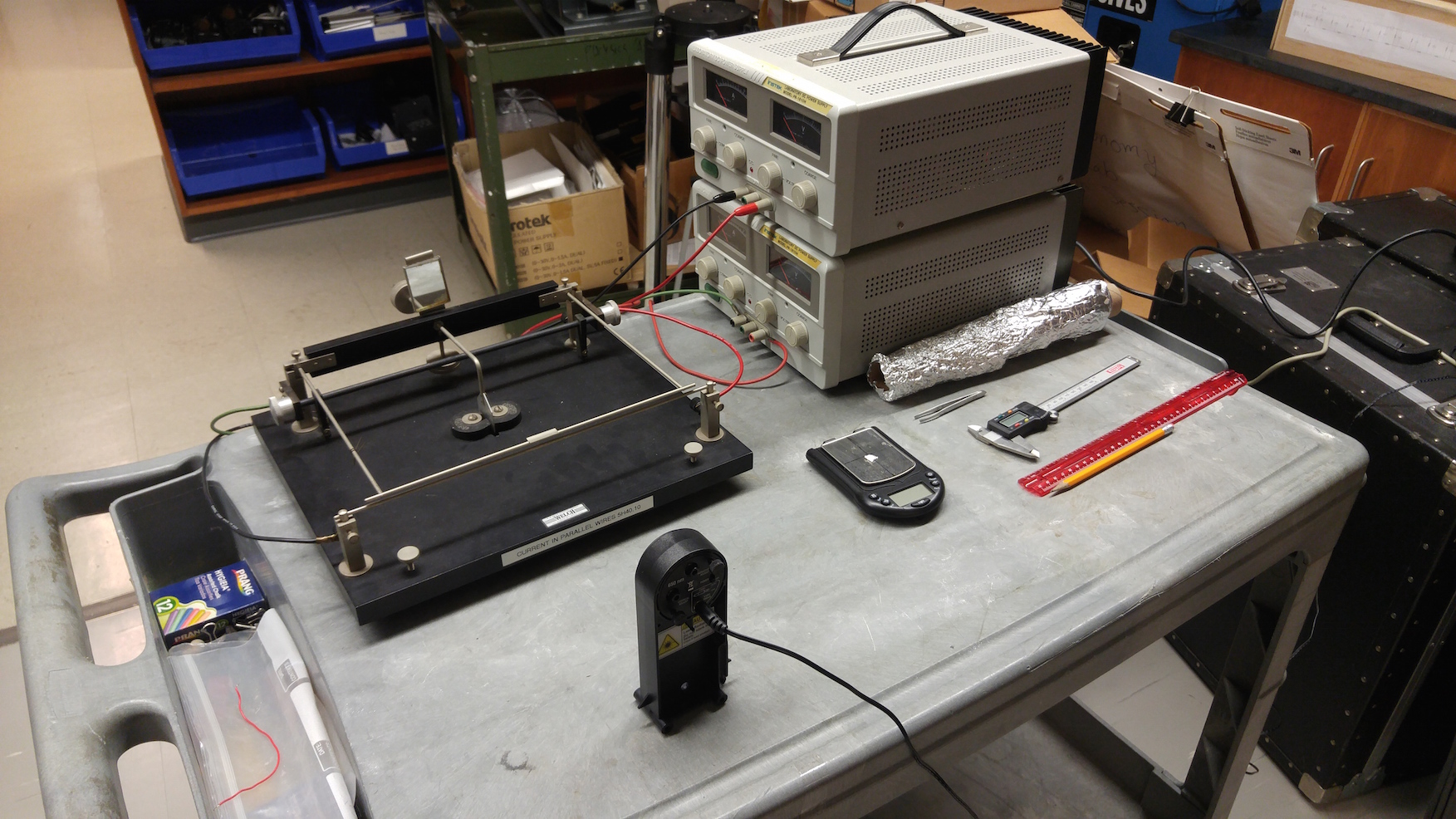
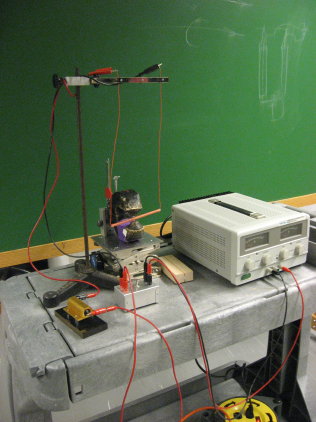
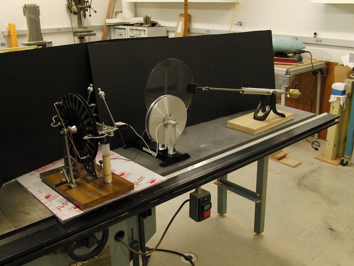
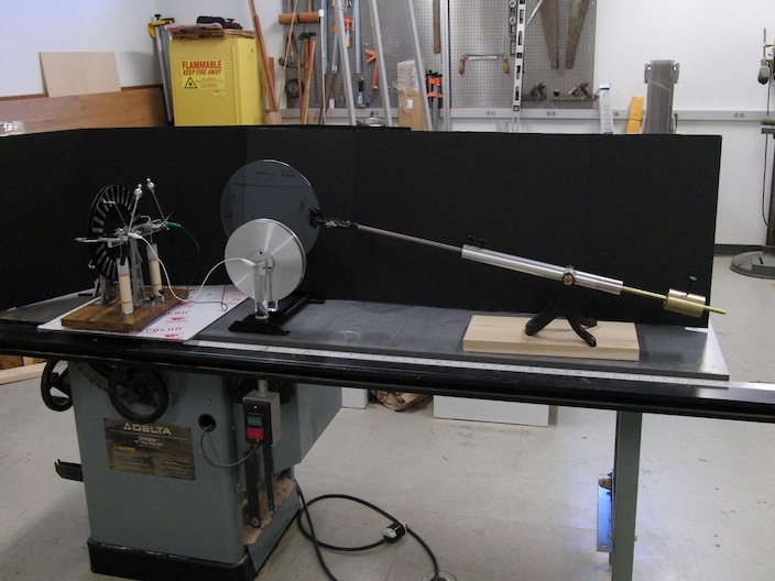
- Demonstrate force between parallel currents.
- Using two power supplies, send current through both stationary and balancing wires.
- Angle of mirror connected to pivot will change as wires are pulled together or pushed apart due to Lorentz force. A laser beam, deflected by mirror, can be used to show the otherwise imperceptible change of mirror angle.
- To determine the strength of the Lorentz force: mark the laser position on a distant wall both with and without current- using current that produces attraction, not repulsion. Then, with current off, place small pieces of folded up tin foil on top of movable wire (using platform on wire) until deflection of laser matches that produced by Lorentz force. Weigh tin foil pieces with sensitive digital scale to determine gravitational force.
- Compare gravitational force to Lorentz force.
- Distance between wires, and wire length, can be measured using ruler. Current can be measured using Ammeter.
- Current balance located in L01, section B3.
- Power supply, laser, digital scale, ammeter, and tin foil in L35.
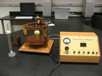

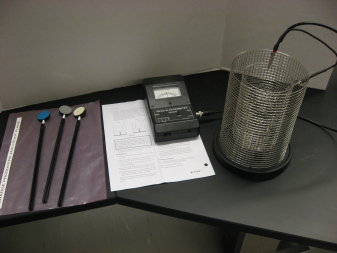
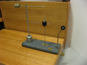
- Demonstrate torque experienced by magnetic dipole in B-field.
- Measure magnetic moment of dipole.
- Show that net force experienced by magnetic dipole
is zero in uniform B-field, and non-zero in B-field with gradient.
- See instructors manual for experimental details.
- Located in L01, section B2.

- Located in L01, section B2
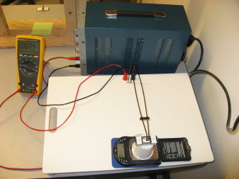

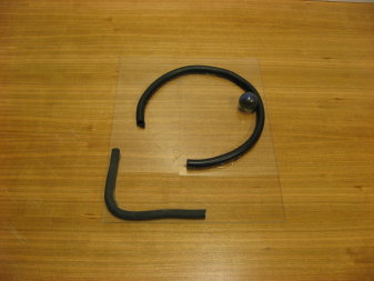
- Purpose: Demonstrate how the magnetic force on a current
carrying wire depends on the angle between the current and the external B-field.
Location
- Current Balance in L01, sectionB3
- Power supply in L35, section F1
- Multimeter in L35, section F3.
- When capacitor is charged by Wimshurst generator, dielectric plate experiences a force, pulling plate into capacitor.
Location
- Capacitor, dielectric plate, and balance arm: L01, section B1.
- Wimshurst generator: L01, Section A2.
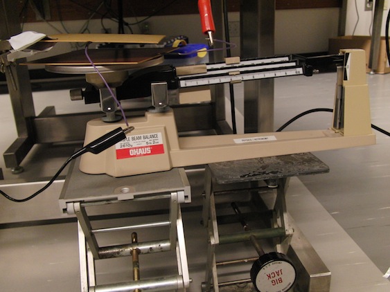

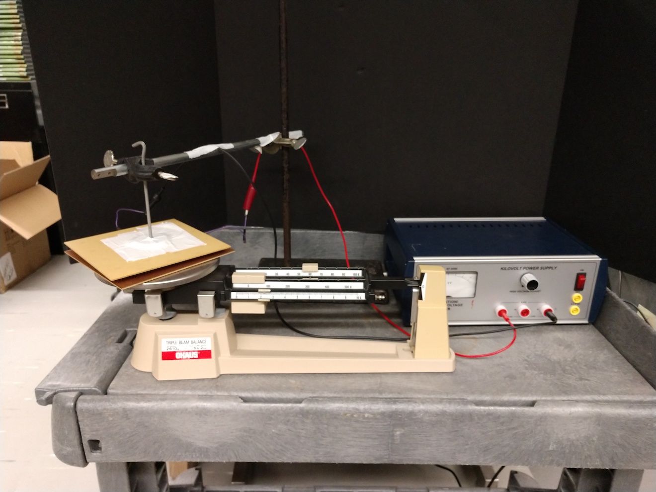
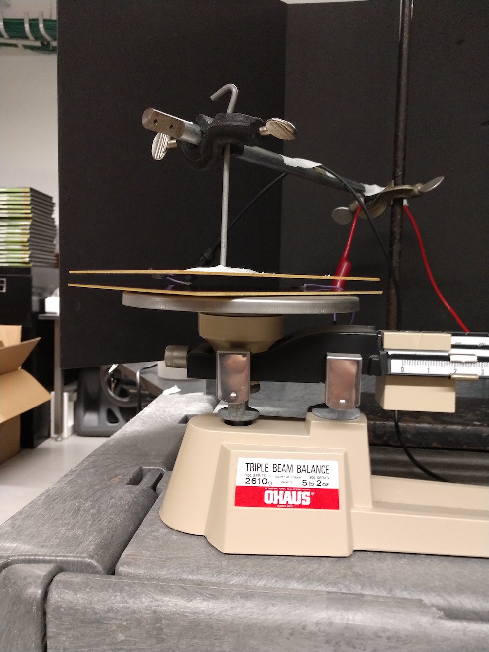
- When Capacitor is charged, plates experience an attractive force.
- Force can be measured by placing one plate on a tripple beam balance, and suspending the other plate directly above the first using a ring stand.
- Capacitor plates are connected to high voltage power supply.
- Compare measured force to theoretical.
Location
- Balance: L35, section D3
- High Voltage Power Supply: L01, section A1
- Capacitor plates with electrodes: L35 section E2
- Lab Jack: L35, section D1
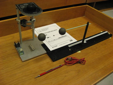

- Demonstrate 1/r^2 dependence of Coulomb force.
- For accurate measurements, potential difference between charged
spheres should be maintained using high-voltage power supply.
- For less-quantitative measurement, spheres can be charged
with rod and fur. Charge on sphere can then be measured using proof plane,
Faraday Ice Pail, and electrometer (right).
Location
- Coulomb Apparatus: L01, section A2.
- Proof plane: L01, section A2, plastic bin.
- Faraday Ice Pail: L01, A2.
- Electrometer: L01, A1.

- When the rolling ball exits the circle it travels in a path
tangential to the circle at the point of exit. The ball, therefore, experiences
no centrifugal force.
- Located in L02, section B3
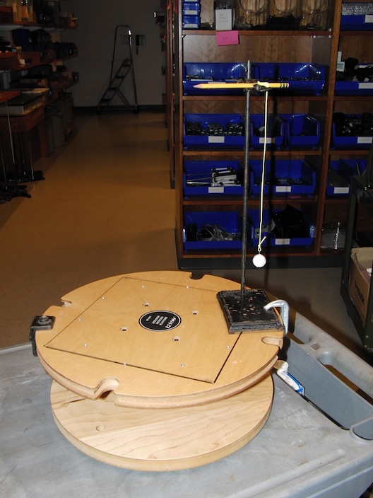

- When turntable spins, ball on string appears to want to fly outward.
Location
- Ball and string- L02, section B3
- Small ring stand- L02, section A1
- Rotating Platform- L02, section D3
- Clamp- L35, section D1
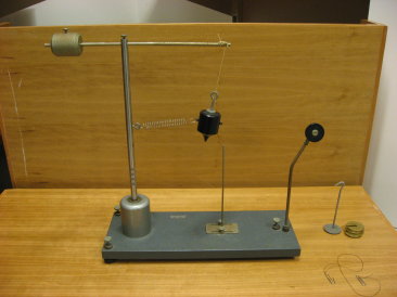

- Apparatus can be used to show that the force acting on an
object in uniform circular motion is equal to mv^2/r, and is always directed
toward the center of the circle.
- Located in L02, section D2. Mass and hangers in L02, section
A1.
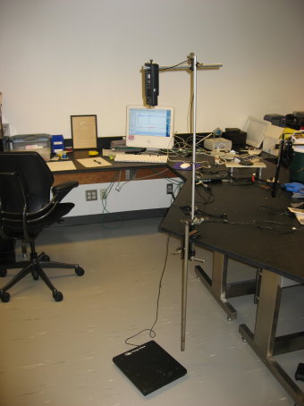

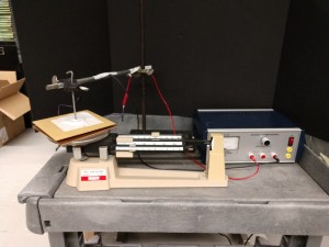
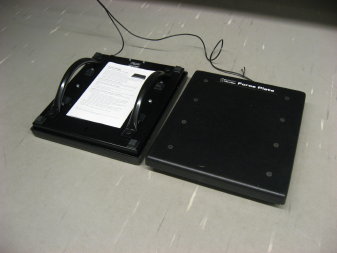
- Measure the drop time of a small plastic ball (or any object
that isn’t so heavy that it damages the force plate upon impact).
- The Pasco force probe is located 1 or 2 meters above the
floor, suspended by a ring stand, oriented with the force sensor pointing
down. A small plastic ball is pressed lightly up against the sensor and then
released. The ball lands on the force plate, resting
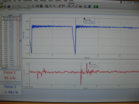
on the floor, directly beneath the force probe. The event is graphed using
logger pro, (in the picture above, the top graph is that of the force probe,
and the bottom the force plate). The moment of release and moment of impact are indicated on the two logger pro graphs. Time measurements are only accurate to
.02 seconds.
- Force probe and labpro device is located in L35, section
B2. Force plate is located in L02 section B3.
- Note: You might think that a photogate would
be the more effective and convenient way to measure the release time. But
for some reason, when the photogate is used drop times are consistently measured
to be .04 seconds too short. Which amounts to about 10% error.
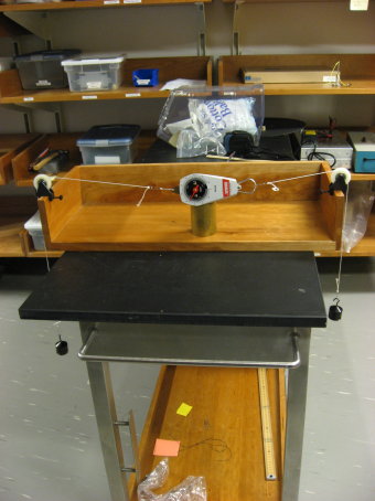

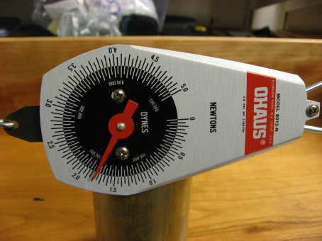
- Spring Scale is connected to two hanging weights. Many students
predict that the value of the scale reading will be the sum of the two weights, not simply the value of one- hence the name “paradoxical”, I guess.
- Located in L02, section B4. Scales and weights in section
A1.

- Use in conjunction with Logger Pro to measure forces in real
time. Use graphical analysis in Logger Pro to demonstrate Newton’s Laws. Durable
enough to leap from or push heavy objects.
- Located in L02, section B3, in plastic tub.