Victorian Bulb

0606181617a_HDR

  • The Victorian light bulb (a replica of Thomas Edison’s original design) contains a long, visible, carbon filament.
  • When a neodymium magnet is brought into close proximity of the bulb, the field of the magnet causes the filaments to vibrate at 60 Hz (the frequency of AC current in the filaments).

0606181619b_HDR

  • Bulb located in L01, section B3 (in a small, labeled box).
  • Lamp cord in L35, section D2.

Jumping Wire / Parallel Currents


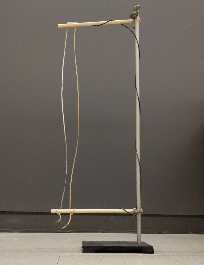
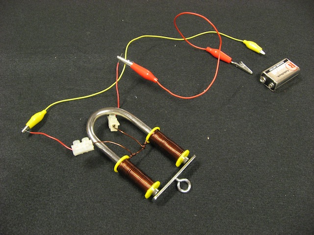
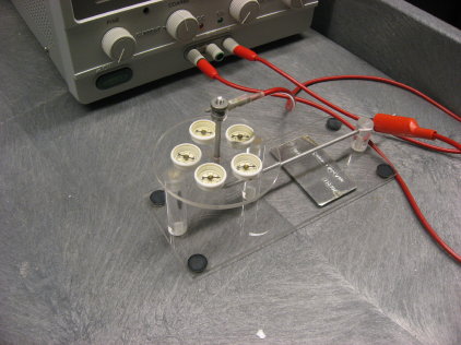
High current from the jump starter makes the wires jump together or apart, depending on how the circuit is wired.  Connections are set up so that the clamps can be attached to the bottoms of the two lamp wires for antiparallel currents (series) or so that one clamp can be connected to the black-coated third wire and the other to the two lamp wires together for parallel currents.

Make sure not to leave the current on for very long, as the wires will get hot enough to melt the insulation.  The instructions for the jump starter say to leave it plugged in when it’s not in use.

Location: L01, section B2

Jumping Ring

Both the old jumping ring and the new jumping ring apparatus.

Jumping Ring demo picture

  • Fluctuating B field causes ring to either 1) jump off of apparatus, or 2) levitate. 
  • For new apparatus (right in top picture): plug into wall and push the switch on the right down to let current flow. For old apparatus (left in top picture): plug Apparatus into variac; turn variac knob to set current amount; flip variac switch to “on” position to produce instantaneous B field.
  • For added excitement, cool rings with LN2 to increase conductivity.

Notes about use

  • For old apparatus: apparatus is pretty old. Iron rods not securely connected to wooden base. Hold onto base and rods, when lifting or transporting.
  • Do not touch apparatus when current is flowing (variac on or switch pressed).
  • Jumping ring apparatus located in L01, section B2. Variac
    located in L01, section A1.

Electromagnet


Electromagnet demo picture

  • Connect a 9V battery ( or power supply) to copper wire coils to create a horseshoe magnet. Vary current to vary strength of magnetic force.
  • Strength of force can be measured using plate with hook (shown above), and spring force scale (L02, section A-1).
  • Located in L01, section


Current in Solenoid


Current in Solenoid demo picture

  • Purpose: Illustrate principles of electro-magnetic induction.
  • Send current through solenoid and measure direction of B-field
    using B-field indicator (magnaprobe). Place coil of wire in front of solenoid
    and quickly adjust current; galvanometer will indicate induced emf consistent
    with Lenz’s law.

Location

  • Solenoid and wire coil located in L01, section B2.
  • Power supply- L35, section F1;
  • magnaprobe- L35, section E4, top shelf
  • galvanometers- L35, section F3


Force on Wire


Force on Wire demo picture
Force on Wire demo picture 2

  • Straight, rigid wire hangs between poles of strong magnet.
    When current is sent through wire, wire is deflected. Direction of deflection
    depends on direction of current.
  • For setup assistance, ask Lab Lecturer.


Parallel Currents

Parallel Currents demo picture

force on parallel wires

  • Demonstrate force between parallel currents.
  • Using two power supplies, send current through both stationary and balancing wires.
  • Angle of mirror connected to pivot will change as wires are pulled together or pushed apart due to Lorentz force. A laser beam, deflected by mirror, can be used to show the otherwise imperceptible change of mirror angle.
  • To determine the strength of the Lorentz force: mark the laser position on a distant wall both with and without current- using current that produces attraction, not repulsion. Then, with current off, place small pieces of folded up tin foil on top of movable wire (using platform on wire) until deflection of laser matches that produced by Lorentz force. Weigh tin foil pieces with sensitive digital scale to determine gravitational force.
  • Compare gravitational force to Lorentz force.
  • Distance between wires, and wire length, can be measured using ruler. Current can be measured using Ammeter.
  • Current balance located in L01, section B3.
  • Power supply, laser, digital scale, ammeter, and tin foil in L35.


Current Balance


Current Balance demo picture

  • Purpose: Demonstrate how the magnetic force on a current
    carrying wire depends on the angle between the current and the external
    B-field.

Location

  • Current Balance in L01, sectionB3
  • Power supply in L35, section F1
  • Multimeter in L35, section F3.


B-field of Current


B-Field of Current demo picture

  • Purpose: Illustrate shape of B-field around current carrying
    wires and show similarities to B-field produced by permanent magnets.

Location

  • Field demonstrators, iron filings, solenoid, perm. magnets,
    mini-compass: L01-section B2
  • Power supply: L35-section F1


Lemon Battery


Lemon Battery demo photo
Lemon Battery demo photo 2

  • Insert a copper and a zinc electrode into lemon; connect electrodes to multimeter. Experiment with different electrodes.
  • Electrodes located in L01, section B3; multimeter in section
    A1.