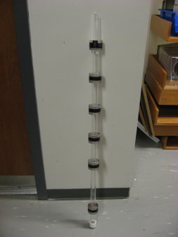
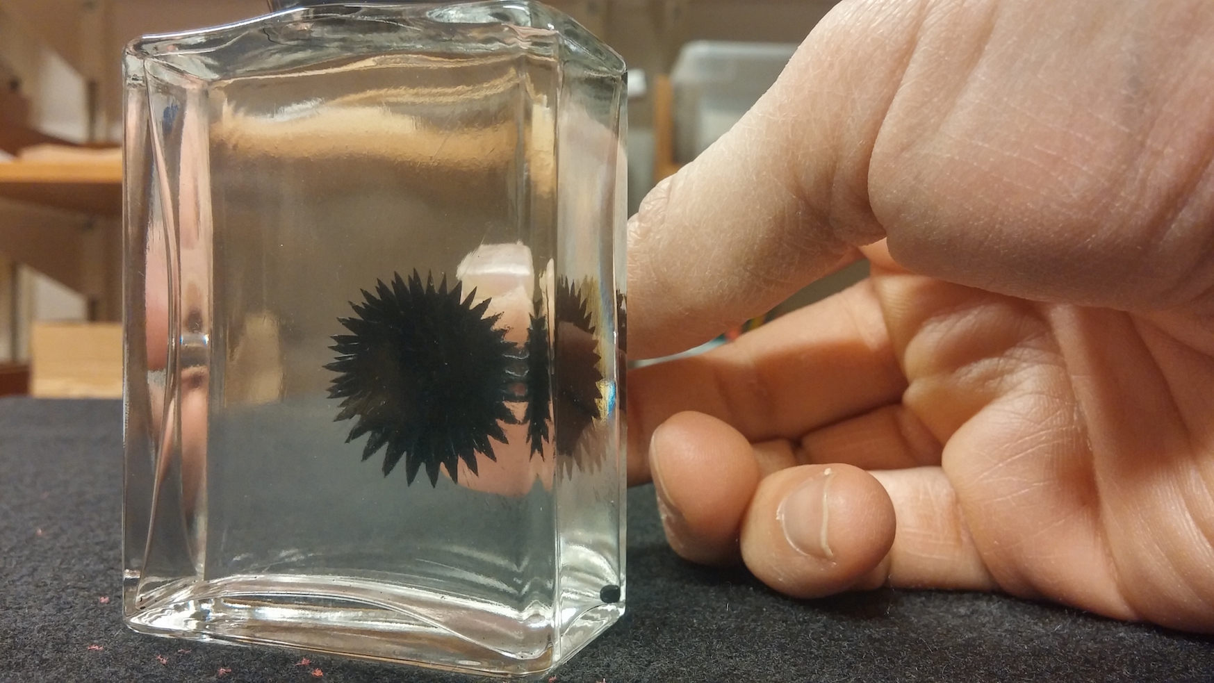
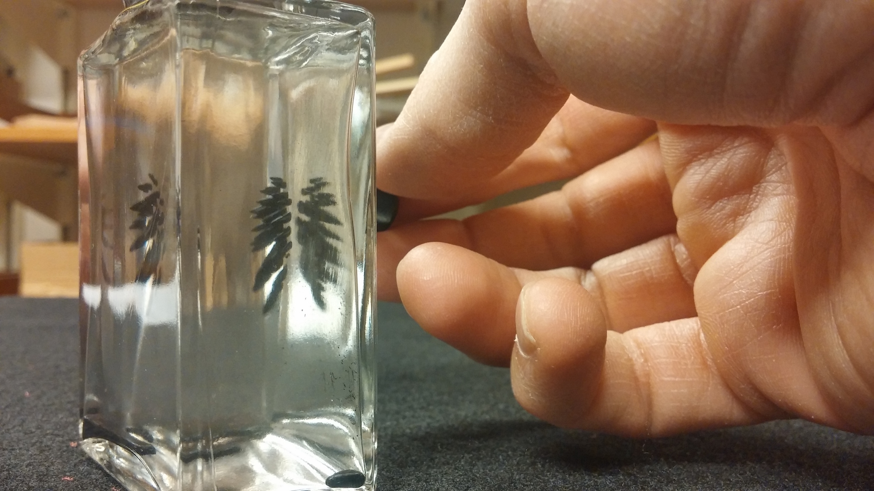
Lenz’s Law Pipe


Induction Pipe

  • Use Lenz’s law to explain extremely slow descent of neodymium
    magnet through copper pipe.
  • Hold pipe in a vertical orientation; drop magnet through
    top opening of pipe; watch descent through holes in pipe.
  • Try pipe with continuous slit to see difference in effect.
  • Use copper slug to show speed of descent of non magnetic object.

Location

  • Pipes located in L01, right-hand side between A2 and B1.
  • Magnet in L01, section B2.


Lenz’s Law Pendulum


Lenz's Law Pendulum demo picture

  • Purpose: Demonstrate the effect of eddy currents on motion of metal pendulum in strong B-field.
  • Pendulum accessories include two interchangeable copper plates, one of which is serrated. Serrated copper plate experiences little resistance to motion through magnetic field.
  • Located in L03


Crude Generator and Motor


Crude Generator and Motor demo picture

  • Purpose: Demonstrate the importance of electromagnetic induction
    in the operation of generators and motors.
  • Motors (right photo) consist of small coils of wire suspended
    above niodym-magnets; coils rest upon bent wires, and bent wires are connected,
    via clip leads, to a battery pack.
  • Generator (left photo) consists of a small coil of wire suspended
    above a niodymium magnet; coil rests upon leads which are connected to a multimeter.

Location

  • Generators and Motors located in L01, section B4
  • Multi-meter in L35, section F3
  • Battery packs in L35, section E1.
  • Clip-clip cables in L35, section E3


Magnet and Solenoid


Magnet and Solenoid demo picture

  • Purpose: Demonstrate that changing magnetic flux induces emf.
  • Push magnet into solenoid and galvanometer needle deflects, indicating induced emf; pull magnet out of solenoid and galvanometer needle deflects the opposite way.

Location

  • Solenoid and magnet:L01, section B2
  • Galvanometer: L35, section F3


Current in Solenoid


Current in Solenoid demo picture

  • Purpose: Illustrate principles of electro-magnetic induction.
  • Send current through solenoid and measure direction of B-field
    using B-field indicator (magnaprobe). Place coil of wire in front of solenoid
    and quickly adjust current; galvanometer will indicate induced emf consistent
    with Lenz’s law.

Location

  • Solenoid and wire coil located in L01, section B2.
  • Power supply- L35, section F1;
  • magnaprobe- L35, section E4, top shelf
  • galvanometers- L35, section F3


Wire loop in B-field

Wire loop in B-field demo picture

  • Purpose: Illustrate that a changing magnetic flux induces an emf.
  • Use a B-field indicator, or compass, to show direction of B-field around magnet; connect coil of wire to galvanometer and move coil in and out of B-field to deflect galvanometer needle.
  • Location: magnet and coil located in L01; galvanometers are in L35, shelf F3, in plastic bin.


Electromagnet


Electromagnet demo picture

  • Connect a 9V battery ( or power supply) to copper wire coils to create a horseshoe magnet. Vary current to vary strength of magnetic force.
  • Strength of force can be measured using plate with hook (shown above), and spring force scale (L02, section A-1).
  • Located in L01, section


Lorentz Force


Lorentz Force demo picture

Lorentz Force demo picture 2

Demonstrate Magnetic force on current carrying wire.


Location:

  • Neodymium magnet- L35, section E2.
  • Wire: Section E3
  • Ring Stand: Section A4
  • Battery: Electronics Shop.

Note: Blue wire is taped to pencil (with masking tape) for stability.
Clip-clip leads connect battery to wire.


Force on Wire


Force on Wire demo picture
Force on Wire demo picture 2

  • Straight, rigid wire hangs between poles of strong magnet.
    When current is sent through wire, wire is deflected. Direction of deflection
    depends on direction of current.
  • For setup assistance, ask Lab Lecturer.


e-beam in B-field


e-beam in Bfield demo picture

Purpose: Demonstrate the magnetic deflection of an electron
beam.

  • Crookes tube contains a white screen that fluoresces green when electrons collides with it. High voltage applied across the anode and cathode accelerate electrons through tube. Electron beam can be deflected using magnetic field of bar magnet.

ALWAYS USE THE MINIMUM VOLTAGE AND CURRENT NECESSARY TO OPERATE CROOKES TUBE.

Location

  • Crookes Tube: L01, section B3
  • Kilovolt Power Supply: L01, section A1
  • Magnet: L01, section B2
  • Cables: L01, or L35 (hanging on wall)