Dynamo

  • Use a power supply (not shown) to run current through the 0.1m coils. Use the power supply shown to spin up disk to approx. 4000 rpm (Mike Brown can tell you how to determine the rpm). A potential difference between the outer rim of the wheel and the axel is induced and can be measured using a voltmeter.
  • Located in storage room, L-50.

Induction Solenoids

Induction coils

0309181127


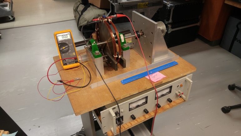
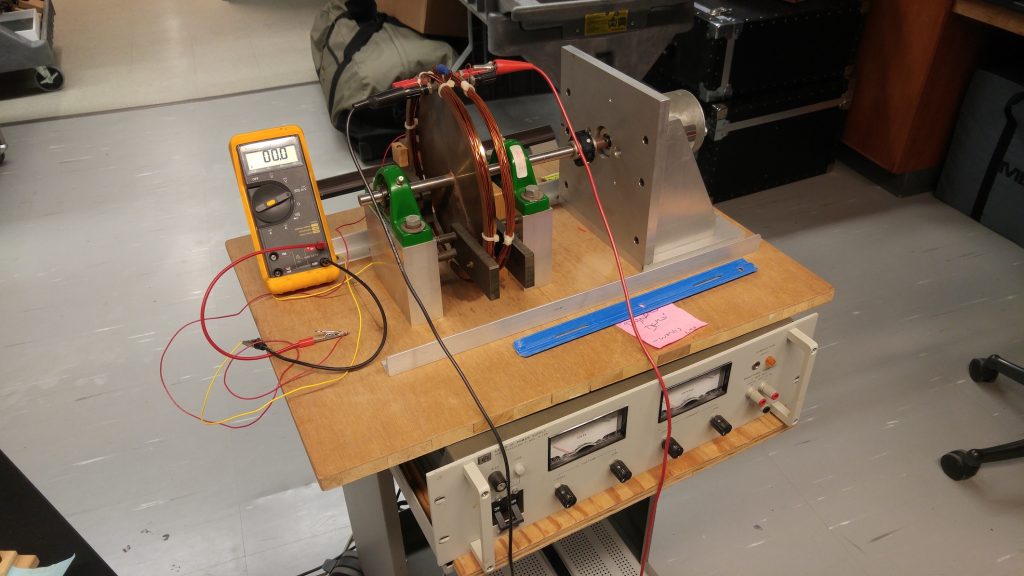
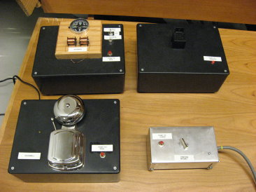
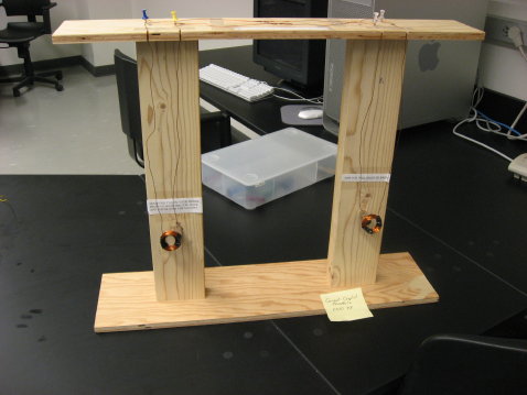
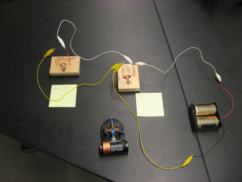
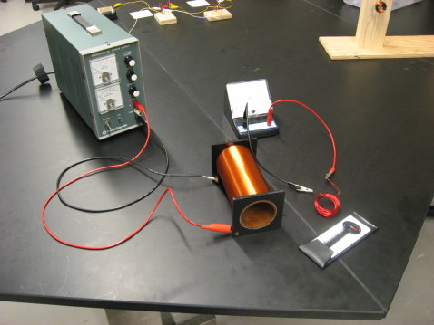
  • When current through a solenoid changes, a magnetic field is induced within the solenoid. If two solenoids are concentric with each other, the induced field in one solenoid produces a changing current in the other.
  • Connect a power supply to one solenoid and a galvanometer to the other.
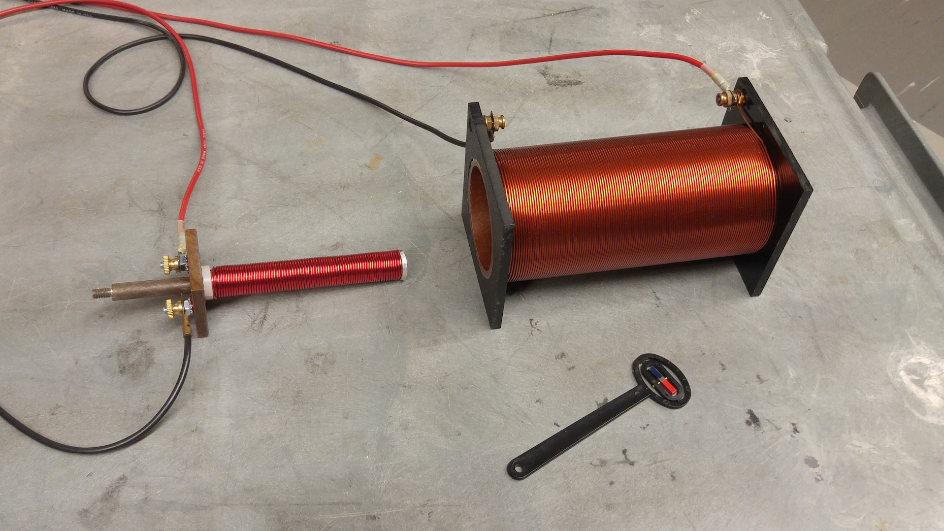
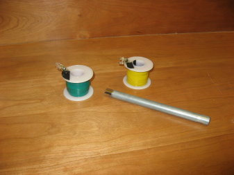
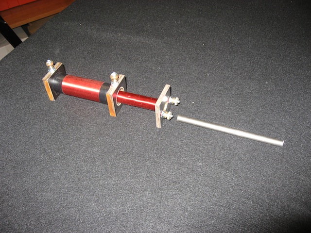
  • Unless steel rod is inserted in innermost cylinder (shown above), induced magnetic field is too week to produce a noticeable effect. Steel rod greatly enhances effect.

Location

Solenoids: L01, section B-2

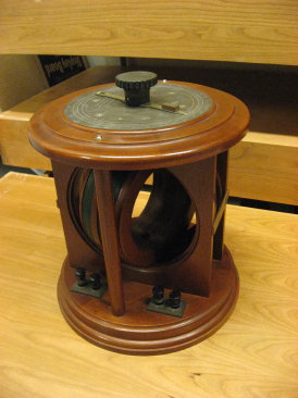
Galvanometer: L35, section F-3

Power supply: L35, section F-1


Crude Generator and Motor


Crude Generator and Motor demo picture

  • Purpose: Demonstrate the importance of electromagnetic induction
    in the operation of generators and motors.
  • Motors (right photo) consist of small coils of wire suspended
    above niodym-magnets; coils rest upon bent wires, and bent wires are connected,
    via clip leads, to a battery pack.
  • Generator (left photo) consists of a small coil of wire suspended
    above a niodymium magnet; coil rests upon leads which are connected to a multimeter.

Location

  • Generators and Motors located in L01, section B4
  • Multi-meter in L35, section F3
  • Battery packs in L35, section E1.
  • Clip-clip cables in L35, section E3


Current in Solenoid


Current in Solenoid demo picture

  • Purpose: Illustrate principles of electro-magnetic induction.
  • Send current through solenoid and measure direction of B-field
    using B-field indicator (magnaprobe). Place coil of wire in front of solenoid
    and quickly adjust current; galvanometer will indicate induced emf consistent
    with Lenz’s law.

Location

  • Solenoid and wire coil located in L01, section B2.
  • Power supply- L35, section F1;
  • magnaprobe- L35, section E4, top shelf
  • galvanometers- L35, section F3