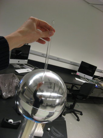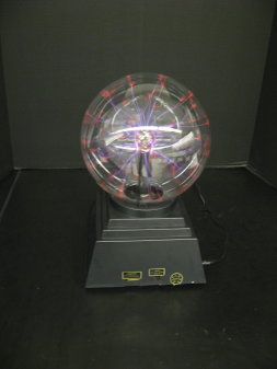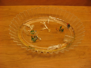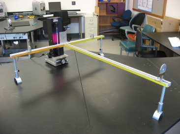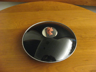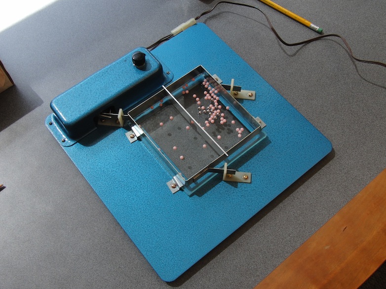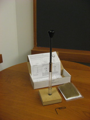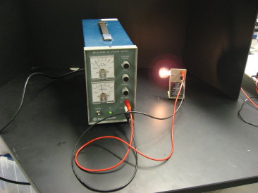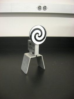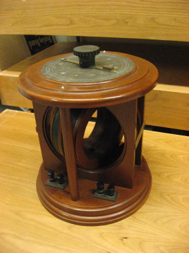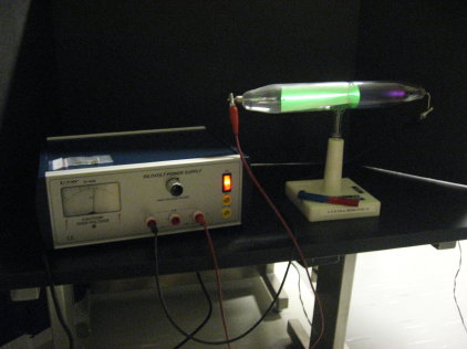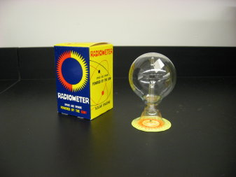
- Temperature difference at edge of metal vanes causes rotor
to spin.
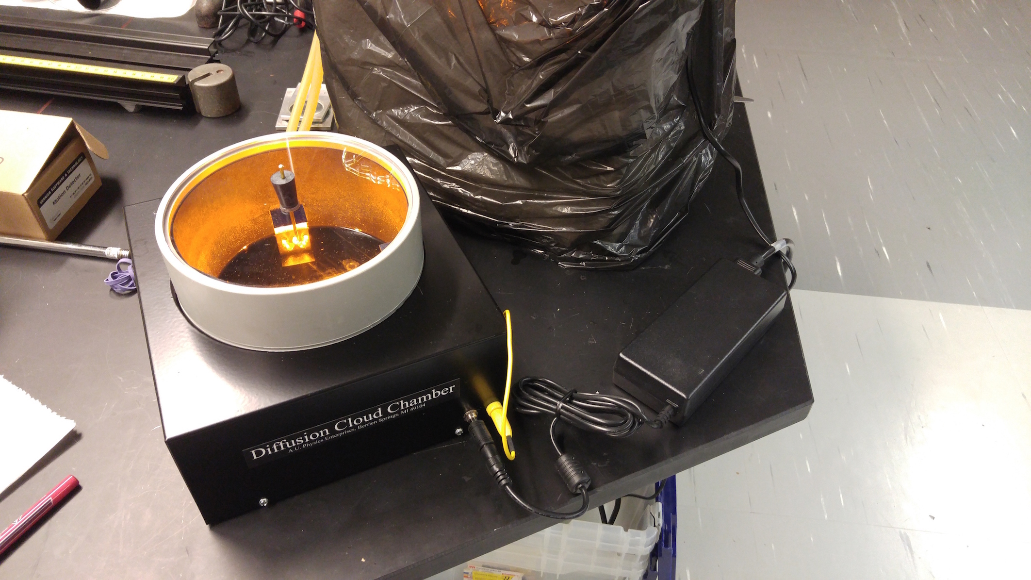
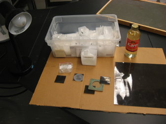
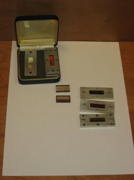
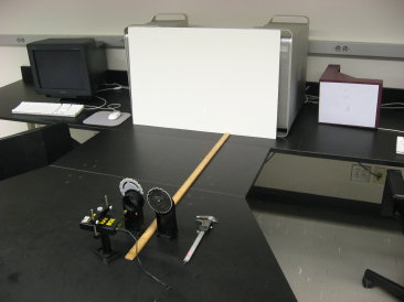
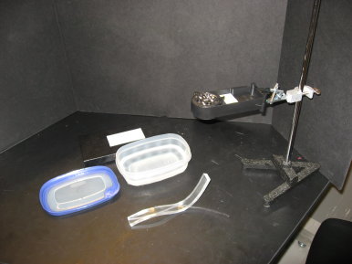
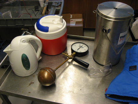
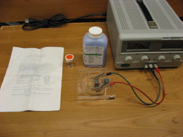
- Located in L02, section C3
- Below explanation taken from Wikipedia (so it must be true).
–Explanations for the force on the vanes–
Over the years, there have been many attempts
to explain how a Crookes radiometer works:
1. Crookes incorrectly suggested that the force was due to the pressure of light.
This theory was originally supported by James Clerk Maxwell who had predicted
this force. This explanation is still often seen in leaflets packaged with the
device. The first experiment to disprove this theory was done by Arthur Schuster
in 1876, who observed that there was a force on the glass bulb of the Crookes
radiometer that was in the opposite direction to the rotation of the vanes.
This showed that the force turning the vanes was generated inside the radiometer.
If light pressure was the cause of the rotation, then the better the vacuum
in the bulb, the less air resistance to movement, and the faster the vanes should
spin. In 1901, with a better vacuum pump, Pyotr Lebedev showed that in fact,
the radiometer only works when there is low pressure gas in the bulb, and the
vanes stay motionless in a hard vacuum. Finally, if light pressure were the
motive force, the radiometer would spin in the opposite direction as the photons
on the shiny side being reflected would deposit more momentum than on the black
side where the photons are absorbed. The actual pressure exerted by light is
far too small to move these vanes but can be measured with devices such as the
Nichols radiometer.
2. Another incorrect theory was that the heat on the dark side was causing the
material to outgas, which pushed the radiometer around. This was effectively
disproved by both Schuster’s and Lebedev’s experiments.
3. A partial explanation is that gas molecules hitting the warmer side of the
vane will pick up some of the heat, bouncing off the vane with increased speed.
Giving the molecule this extra boost effectively means that a minute pressure
is exerted on the vane. The imbalance of this effect between the warmer black
side and the cooler silver side means the net pressure on the vane is equivalent
to a push on the black side, and as a result the vanes spin round with the black
side trailing. The problem with this idea is that while the faster moving molecules
produce more force, they also do a better job of stopping other molecules from
reaching the vane, so the net force on the vane should be exactly the same —
the greater temperature causes a decrease in local density which results in
the same force on both sides. Years after this explanation was dismissed, Albert
Einstein showed that the two pressures do not cancel out exactly at the edges
of the vanes because of the temperature difference there. The force predicted
by Einstein would be enough to move the vanes, but not fast enough.
4. The final piece of the puzzle, thermal transpiration, was theorized by Osborne
Reynolds, but first published by James Clerk Maxwell in the last paper before
his death in 1879. Reynolds found that if a porous plate is kept hotter on one
side than the other, the interactions between gas molecules and the plates are
such that gas will flow through from the cooler to the hotter side. The vanes
of a typical Crookes radiometer are not porous, but the space past their edges
behave like the pores in Reynolds’s plate. On average, the gas molecules move
from the cold side toward the hot side whenever the pressure ratio is less than
the square root of the (absolute) temperature ratio. The pressure difference
causes the vane to move cold (white) side forward.
Both Einstein’s and Reynolds’s forces appear to cause a Crookes radiometer to
rotate, although it still isn’t clear which one is stronger.